The manipulation pipeline has been released; THIS DEMO PAGE IS NOW DEPRECATED. For current information on the manipulation pipeline, and information about how to execute pick and place tasks using ROS and the PR2 see the pr2_tabletop_manipulation_apps stack page and the pr2_pick_and_place_demos package.
This was central repository for the PR2 manipulation demo that was shown at ICRA 2010.

Overview
In a nutshell, this demo shows pick-and-place capabilities using the PR2. The robot will pick up objects from one side of a table surface and place them back down on the other side of the table. This demo is designed to run continuously (obviously, if all goes well and keeps going well), with no need for human intervention.
This demo is not intended to showcase the application itself (which is fairly simple). Rather, it is primarily an integration demo, meant to show:
- the hardware abilities of the PR2 platform and its array of sensors;
- the large number of available ROS packages for low- and mid-level functionality;
- how such packages can be integrated towards achieving higher level functionality;
- that research-grade packages can be combined with release-grade packages to provide insight into a particular problem or sub-problem;
- that the PR2 and ROS provide a solid hardware and software base for achieving higher level applications.
The two take-home system-level messages for the audience are:
- this is fairly complex behavior (for an autonomous robot at least), requiring many software and hardware components;
- if you (the member of the audience) think you can do better on one module of this demo, we'd love for you to publish code that does so.
Regarding the manipulation functionality itself, two main things that we'd like the audience to notice are that:
- we can pick up both known objects (recognized from a database) and unknown objects
- all the operation is collision free, in a largely unstructured environment
On this page we will discuss the functionality itself. More information for setting up and running the demo can be found in the list of tutorials:
- Install the model database server and data on a new robot or machine
Describes how to install and start the PostgreSQL server on a robot. Does not show how to load the actual database onto this server.
- One-line key points to mention during the manipulation demo
A simpler form of the main demo page which describes all the functionality in detail. Think of it as a "cheat-sheet" for remembering the main points that the audience might be interested in.
- Set up the source code tree for the ICRA manipulation demo
Easy-to-follow instructions for downloading and building all the code you need for the manipulation demo on a robot.
- ICRA manipulation demo sync point hierarchy
A list of the sync points used to pause the demo when using the demo joystick controller.
- Running the ICRA manipulation demo
This tutorial explains how to run the ICRA manipulation demo.
The Grasping Pipeline
Chronologically, the process of grasping an object goes through the following stages:
- the target object is identified in sensor data from the environment
- a set of possible grasp points are generated for that object
- a collision map of the environment is built based on sensor data
- a feasible grasp point (no collisions with the environment) is selected from the list
- a collision-free path is generated and executed, taking the arm from its current configuration to a pre-grasp position for the desired grasp point
- the final path from pre-grasp to grasp is executed, using tactile sensors to correct for errors
- the gripper is closed on the object and tactile sensors are used to detect presence or absence of the object in the gripper
- the object is lifted from the table
Placing an object goes through very similar stages. In fact, grasping and placing are mirror images of each other, with the main difference that choosing a good grasp point is replaced by choosing a good location to place the object in the environment.
From a software hierarchy standpoint, the grasping pipeline contains the following:
- low-level modules (C++ APIs)
- object detection
- grasp point generation
- check for feasibility and execute a given grasp point
- check for feasibility and execute a place at a given location
- etc.
- mid-level module (ROS API)
- present a list of graspable objects in a scene
- grasp a given object
- place a grasped object at a given location
- high level module (Python script)
- move objects from one side of the table to the other
The grasping pipeline relies heavily on other ROS packages and stacks, including:
- sensor processing
- stereo camera processing
- robot self-filtering in laser data
- etc.
- arm navigation
- motion planning
- collision avoidance
- trajectory execution
- joint controllers
- etc.
- ROS-SQL interface and a PostgreSQL database containing known object models and pre-computed grasp points
- etc.
The stages of the grasping operation are detailed in the next section.
Grasping Modules Details
Object Perception
There are two main components of object perception:
- object segmentation: which part of the sensed data corresponds to the object we want to pick up?
- object recognition: which object is it?
Our pipeline always requires segmentation. If recognition is performed and is successful, this informs the grasp point selection mechanism. If not, we can still grasp the unknown object based only on perceived data.
Note that it is possible to avoid segmentation as well and select grasp points without knowing object boundaries. The current pipeline does not have this functionality, but it might gain it in the future.
To perform these tasks we rely on two main assumptions:
- the objects are resting on a table, which is the dominant plane in the scene
- the minimum distance between two objects exceeds a given threshold (3cm in our demo)
- in addition, in order to recognize an object, it mush have a known orientation, such as a glass or a bowl sitting "upright" on the table.
The sensor data that we use consists of a point cloud from the narrow stereo cameras. We perform the following steps:
- the table is detected by finding the dominant plane in the point cloud using RANSAC;
points above the table are considered to belong to graspable objects. We use a clustering algorithm to identify individual objects. We refer to the points corresponding to an individual object as clusters.
- for each cluster, a simple iterative fitting technique (a distant cousin of ICP) is used to see how well it corresponds to each mesh in our database of models. If a good fit is found, the database id of the model is returned along with the cluster.
- note that our current fitting method operates in 2D, since based on our assumptions (object resting upright on the known surface of the table) the other 4 dimensions are fixed
The output from this components consists of the location of the table, the identified point clusters, and the corresponding database object id and fitting pose for those clusters found to be similar to database objects.
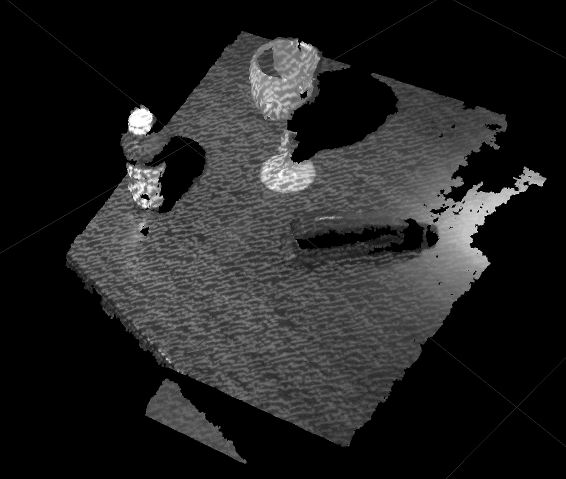
Narrow Stereo image of a table and three objects
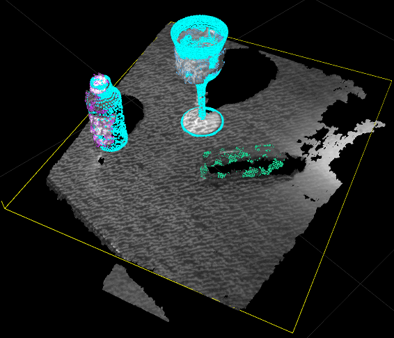
Detection result: table plane has been detected (note the yellow contour). Objects have been segmented (note the different color point clouds superimposed on them). The bottle and the glass have also been recognized (as shown by the cyan mesh further superimposed on them)
Grasp Point Selection
For either a recognized object (with an attached database model id) or an unrecognized cluster, the goal of this component is to generate a list of good grasp points. Here the object to be grasped is considered in isolation: a good grasp point refers strictly to a position of the gripper relative to the object, and knows nothing about the rest of the environment.
For unknown objects, we use a module that operates strictly on the perceived point cluster. Details on this module can be found in the following paper: Contact-Reactive Grasping of Objects with Partial Shape Information that Willow researchers will present at the ICRA Workshop on Mobile Manipulation on Friday 05/07.
For recognized objects, out model database also contains a large number of pre-computed grasp points. These grasp points have been pre-computed using GraspIt!, an open-source simulator for robotic grasping.
The output from this module consists of a list of grasp points, ordered by desirability (it is recommended that downstream modules in charge of grasp execution try the grasps in the order in which they are presented).
Environment Sensing and Collision Map Processing
We have mentioned that the point cloud from the narrow stereo camera is used for object detection. However, the narrow stereo camera provides a very focused view of the environment, good for the target of the grasping task but which might miss other parts of the environment that the robot can collide against. Furthermore, both stereo camera occasionally produce "false positives", meaning spurious points that might make the robot believe obstacles are in its workspace. While we are working on fixing such issues, we are currently using the tilting laser to provide a complete view of the environment for collision planning.
At specified points in the grasping task, a complete sweep is performed with the tilting laser in order to build the Collision Map of the environment. This map is then used for motion planning, grasp feasibility checks, etc. The main implication is that any changes to the environment that happen between map acquisitions are missed by the robot (with the exception of those changes that the robot effects himself, such as moving an object around).
The robot will avoid fixed parts of the environment (such as the table, the monitor stand, etc) as well as the objects that are part of the manipulation demo, but will have problems with very dynamic obstacles, such as people. It is recommended for people (both demonstrators and audience) to avoid interfering with the robot's workspace. We are aware that this is a key limitation of the current system and will be working hard to remove it in the future.
In addition to the Collision Map acquired with the tilting laser, the robot populates the world with Collision Models of the target objects as well as the detected table. These are added to the Collision Map as either exact triangular meshes (in the case of recognized objects) or bounding boxes (for unknown clusters). These are used to replace the corresponding points from the tilting laser. This procedure allows the robot to reason a lot more precisely about the parts of the world that is has more information on.
When the robot is holding an object, the Collision Model for that object is attached to the robot's gripper. As a result, the robot will reason about arm movement such that the grasped object does not collide with something else in the environment.
Note that the Collision Map processing is part of the arm navigation stack, which is already released.
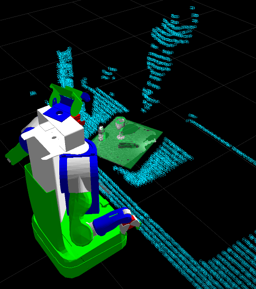
Image of the Collision Map. Note the points from the tilting laser (in cyan) and the explicitly recognized objects (in green)
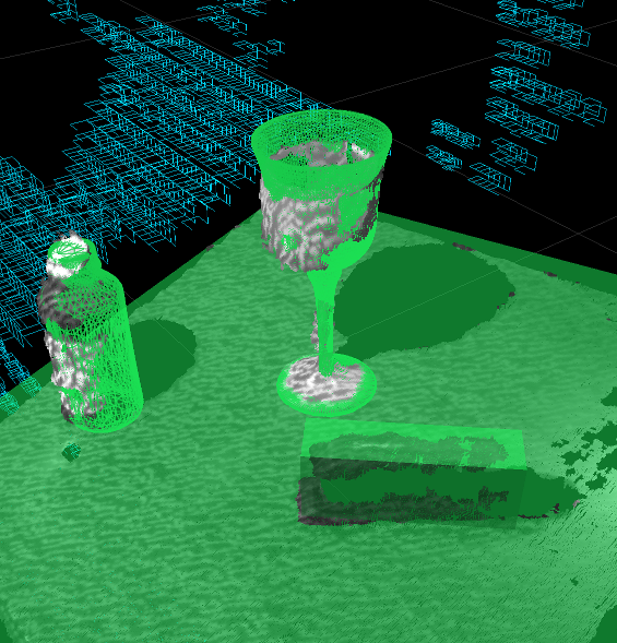
Detail of the Collision Map. Note that the recognized objects have been added as triangle meshes, while the unrecognized object has been added as a bounding box.
Motion Planning
Motion planning is also done using the arm_navigation stack. The algorithm that we use is an RRT variant.
The motion planner reasons about collision in a binary fashion - that is, a state that does not bring the robot in collision with the environment is considered feasible, regardless of how close the robot is to the obstacles. As a result, the planner might compute paths that bring the arm very close to the obstacles. To avoid collisions due to sensor errors or miscalibration, we pad the robot model used for collision detection by a given amount (normally 2cm).
Grasp Execution
The motion planner only works in collision-free robot states. Grasping, by nature, means that the gripper must get very close to the object, and that immediately after grasping, the object, now attached to the gripper, is very close to the table. Since we can not use the motion planner for these states, we introduce the notion of a pre-grasp position: a pre-grasp is very close to the final grasp position, but far enough from the object that the motion planner will compute a path to it. The same happens after pickup: we use a lift position which is far enough above the table that the motion planner can be used from there.
To plan motion from pre-grasp to grasp and from grasp to lift we use an interpolated IK motion planner, while also doing more involved reasoning about which collisions must be avoided and which collisions are OK. For example, during the lift operation (which is guaranteed to be in the "up" direction), we can ignore collisions between the object and the table.
The motion of the arm for executing a grasp is:
      starting_arm_position
               |
               | <-(motion planner)
               |
              \ /
               '
        pre-grasp position
               |
               | <-(interpolated IK)
               |   (with tactile sensor reactive grasping)
              \ /
               '
         grasp position
      (fingers are closed)
(object model is attached to gripper)
               |
               | <-(interpolated IK)
               |
              \ /
               '
         lift position
               |
               | <-(motion planner)
               |
              \ /
               '
some desired arm position 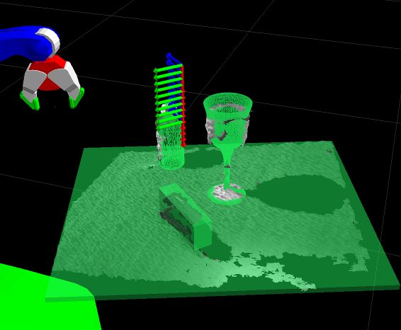
Interpolated IK path from pre-grasp to grasp planned for a grasp point of an unknown object
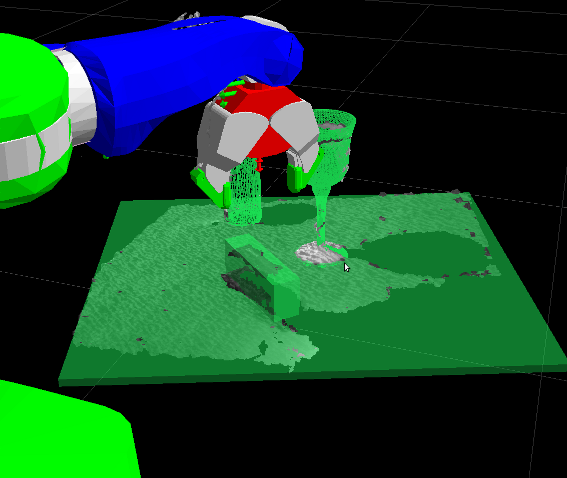
A path to get the arm to the pre-grasp position has been planned using the motion planner and executed.
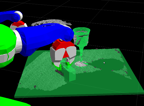
The interpolated IK path from pre-grasp to grasp has been executed.
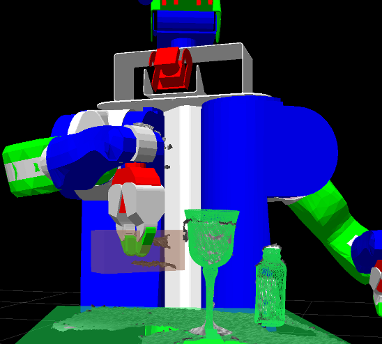
The object has been lifted. Note that the object Collision Model has been attached to the gripper.
Reactive Grasping Using Tactile Sensing
There are many possible sources of error in the pipeline, including errors in object recognition or segmentation, grasp point selection, miscalibration, etc. A common result of these errors will be that a grasp that is thought to be feasible will actually fail, either by missing the object altogether or by hitting the object in an unexpected way and displacing it before the fingers are closed.
We can correct for some of these errors by using the tactile sensors in the fingertips. We use a grasp execution module that slots in during the move from pre-grasp to grasp and uses a set of heuristics to correct for errors detected by the tactile sensors. Details on this module can be found in the following paper: Contact-Reactive Grasping of Objects with Partial Shape Information that Willow researchers will present at the ICRA Workshop on Mobile Manipulation on Friday 05/07.
