Show EOL distros:
Package Summary
razor_imu_9dof is a package on driver for the razor board and 3D display node. The firmware of the razor board is updated and maintained at https://dev.qu.tu-berlin.de/projects/sf-razor-9dof-ahrs/wiki/Tutorial This firmware site had solve many issues created by various version of the board hardware.
- Author: Tang Tiong Yew
- License: BSD
- Source: git https://github.com/robotictang/razor_imu_9dof.git (branch: master)
Package Summary
razor_imu_9dof is a package that provides a ROS driver for the Sparkfun Razor IMU 9DOF. It also provides Arduino firmware that runs on the Razor board, and which must be installed on the Razor board for the system to work. A node which displays the attitude (roll, pitch and yaw) of the Razor board (or any IMU) is provided for testing.
- Maintainer status: maintained
- Maintainer: Kristof Robot <krirobo AT gmail DOT com>
- Author: Tang Tiong Yew, Kristof Robot, Paul Bouchier, Peter Bartz
- License: BSD
- Source: git https://github.com/KristofRobot/razor_imu_9dof.git (branch: hydro-devel)
Package Summary
razor_imu_9dof is a package that provides a ROS driver for the Sparkfun Razor IMU 9DOF. It also provides Arduino firmware that runs on the Razor board, and which must be installed on the Razor board for the system to work. A node which displays the attitude (roll, pitch and yaw) of the Razor board (or any IMU) is provided for testing.
- Maintainer status: maintained
- Maintainer: Kristof Robot <krirobo AT gmail DOT com>
- Author: Tang Tiong Yew, Kristof Robot, Paul Bouchier, Peter Bartz
- License: BSD
- Source: git https://github.com/KristofRobot/razor_imu_9dof.git (branch: indigo-devel)
Package Summary
razor_imu_9dof is a package that provides a ROS driver for the Sparkfun OpenLog Artemis, 9DoF Razor IMU M0, 9DOF Razor IMU and 9DOF Sensor Stick. It also provides Arduino firmware that runs on the board, and which must be installed on it for the system to work. A node which displays the attitude (roll, pitch and yaw) of the board (or any IMU) is provided for testing.
- Maintainer status: maintained
- Maintainer: Fabrice LE BARS <fabrice.le_bars AT ensta-bretagne DOT org>
- Author: Tang Tiong Yew, Kristof Robot, Paul Bouchier, Peter Bartz
- License: BSD, GPLv3
- Source: git https://github.com/ENSTABretagneRobotics/razor_imu_9dof.git (branch: indigo-devel)
Contents
Description
This is a driver package for different Sparkfun Razor IMU 9DOF (Degree of freedom) sensor boards. The Razor boards contain a 3-axis magnetometer, gyro and accelerometer. The driver should also work with Sparkfun sensor sticks, but you will have to figure out how to connect the sensor stick to the Arduino and modify the firmware appropriately - the maintainer of this package will not support you. Older versions of the Razor are not supported.
The Razor has an onboard Arduino which runs Attitude Heading Reporting System (AHRS) firmware that works with this ROS driver. You have to load the ROS AHRS firmware onto it using the Arduino IDE (the board as shipped from Sparkfun only contains sensor-value-printing firmware). The ROS version of the AHRS firmware is in this package, and is derived from the original AHRS Razor firmware by Peter Bartz. The original source was here and an excellent tutorial is on the corresponding wiki page.
A 3D visualization testing application is included in this package.
Sensor Fusion Algorithm
Inside the Razor, the fusion of accelerometer, magnetometer and gyroscope data is done using a Direction Cosine Matrix (DCM) algorithm. The algorithm also takes care of handling sensor noise and numerical errors. It is based on this paper by William Premerlani. For even more detailed information have a look at these papers by Robert Mahony.
Video
The video below shows the included diagnostic GUI in use. It also shows a robot run 5 meters out then back, and shows the corresponding track computed from odometry alone, and also as computed from odometry fused with the IMU using the robot_pose_ekf package.
The steps below describe how to assemble an Attitude and Heading Reference System (AHRS) which does not cost much (US$100) and which publishes ROS Imu messages for consumption by packages like robot_pose_ekf.
Hardware
You need:
The 9 Degrees of Freedom - Razor IMU board (or compatible). Currently the firmware supports different boards from SparkFun (refer to source code). Older versions are not supported.
- Depending on the board version : a corresponding USB cable or a FTDI Basic Breakout - 3.3V board (or compatible) and a USB mini-B cable to connect it to your computer. You'll also want a pin header (6-position single row) to connect the FTDI Basic Breakout board to the Razor board. Use a right-angle header if you want the boards to be coplanar or a straight header if you want them to mount at right angles to each other. Solder the pin header or FTDI cable to the Razor board. Plug the FTDI Basic Breakout board onto the pin header; be sure to orient it correctly - match up the pin labels on the Razor and Basic breakout board.
- Alternatively using an FTDI Cable instead of the breakout board should also work, but be sure to get the 3.3V version.
Software Installation
Install the pre-requisites needed to build and load firmware on the board and to run the Razor node and test GUI.
Required: Arduino IDE. You will use it to upload the firmware and calibrate the sensors. Tested with Arduino IDE 1.8.13.
Optional: Visual Python. Required for the 3D visualization node.
sudo apt-get install python-visual # For Ubuntu 16.04 and before
# For Ubuntu 18.04, install https://github.com/lebarsfa/visual/tree/bionic, or see https://github.com/ENSTABretagneRobotics/razor_imu_9dof/issues/47
sudo apt-get install python3-pip python3-wxgtk4.0 ; pip3 install vpython # From Ubuntu 20.04
Install ROS razor_imu_9dof Package
From Source
Clone the ROS source repository and build it:
cd catkin_ws/src
git clone https://github.com/ENSTABretagneRobotics/razor_imu_9dof.git
cd ..
catkin_make
# For 3D visualization, from Ubuntu 20.04
cd src/razor_imu_9dof/nodes ; wget https://www.glowscript.org/docs/VPythonDocs/VPtoGS.py ; python3 VPtoGS.py ; cp -f Converted/display_3D_visualization.py display_3D_visualization.py ; cd ../../..
From Repository
Install the razor_imu_9dof package from repository, e.g. for Indigo:
sudo apt-get install ros-indigo-razor-imu-9dof
Load Firmware into Razor Board
In this step you copy the Razor firmware from the ROS package and build it and load it into the board using the Arduino IDE.
If you haven't done so before, start the Arduino IDE. It creates a directory in your home for Arduino source code; version 1.0 creates a directory called "sketchbook" and version 1.5 creates a directory called "Arduino". This is where the Arduino IDE expects to find source code for the firmware you're going to install on the Razor.
Copy the Razor firmware from the razor_imu_9dof/src directory to your arduino source directory.
roscd razor_imu_9dof
cp -r src/Razor_AHRS ~/Arduino
Replace ~/Arduino with ~/sketchbook if needed.
- Plug the Razor USB cable into your ROS workstation
- Restart the Arduino IDE
Open the Razor_AHRS sketch in Arduino. Select the Razor_AHRS tab.
- In Arduino:
Look at the top of the Razor_AHRS.ino file, it contains useful information about the firmware.
There is a section labeled "USER SETUP AREA" where you can set some firmware defaults, including the board type.
Caution: choose the correct Razor hardware revision when compiling and uploading the firmware to the board. The setting is located in Razor_AHRS.ino under "HARDWARE OPTIONS"!
For SPX-15846 and DEV-16832 (OpenLog Artemis), you will need to follow the same instructions as for the OLA_IMU_Basics.ino sample from https://github.com/sparkfun/OpenLog_Artemis (i.e. get the drivers from https://learn.sparkfun.com/tutorials/how-to-install-ch340-drivers, install SparkFun Apollo3 boards in Arduino IDE as in https://learn.sparkfun.com/tutorials/installing-board-definitions-in-the-arduino-ide (add https://raw.githubusercontent.com/sparkfun/Arduino_Boards/master/IDE_Board_Manager/package_sparkfun_index.json to File → Preferences → Additional Board Manager URLs) and ensure you select SparkFun Apollo3 → SparkFun RedBoard Artemis ATP as the board and install SparkFun ICM 20948 IMU Arduino library as in https://learn.sparkfun.com/tutorials/installing-an-arduino-library). For SEN-14001 (9DoF Razor IMU M0), you will need to follow the same instructions as for the default firmware on https://learn.sparkfun.com/tutorials/9dof-razor-imu-m0-hookup-guide and use an updated version of SparkFun_MPU-9250-DMP_Arduino_Library from https://github.com/lebarsfa/SparkFun_MPU-9250-DMP_Arduino_Library (an updated version of the default firmware is also available on https://github.com/lebarsfa/9DOF_Razor_IMU). For older board versions, go to "Tools" → "Board" and select "Arduino Pro or Pro Mini (3.3v, 8mhz) w/ATmega328". Note: in Aduino 1.5+, the board menu doesn't allow selecting the voltage/frequency; go to the Processor menu after selecting "Arduino Pro or Pro Mini" and select "ATMega 328 (3.3V, 8Mhz)"
Go to "Tools" → "Serial Port" and select the port used with the Razor.
Go to "File" and hit "Upload to I/O Board". After a short while at the bottom of the *Arduino* code window it should say "Done uploading".
Create Configuration File
Create a custom configuration file my_razor.yaml:
Copy the template file razor.yaml:
roscd razor_imu_9dof/config
cp razor.yaml my_razor.yaml
Edit my_razor.yaml as needed. See further for more information on setting the calibration values.
Coordinate Frames
The definition of the coordinate frame used by the Razor_AHRS firmware differs from what is printed on the board and also from the ROS coordinate frame. You will be exposed to these differences when testing the Razor AHRS and ROS topic output in the testing section below.
The Razor_AHRS firmware uses:
X axis pointing forward (towards the short edge with the connector holes for SEN-10736 and older board versions, see https://github.com/lebarsfa/razor-9dof-ahrs/issues/2 for more information)
- Y axis pointing to the right
- Z axis pointing down
Ignore the labelling on the board and use this coordinate frame when mounting the Razor.
This produces a right-handed coordinate system. However, this is different from ROS' right-handed coordinate frame defined in REP-103, which uses:
X axis pointing forward (towards the short edge with the connector holes for SEN-10736 and older board versions, see https://github.com/lebarsfa/razor-9dof-ahrs/issues/2 for more information)
- Y axis pointing to the left
- Z axis pointing up
The ROS coordinate frame is rotated 180 degrees around the X axis relative to the Razor_AHRS coordinate frame. The razor_imu_9dof node transforms the Razor_AHRS measurements into the ROS coordinate frame. Caution: it is easy to get confused when viewing data from the Razor_AHRS on a serial monitor and from the ROS /imu topic. Think hard!
Testing the AHRS
Serial Monitor
To test by staring at numbers, bring up the Serial Monitor of Arduino under "Tools" → "Serial Monitor". Set it to 57600 baud and send the string "#o1" to the AHRS. You should get output that looks like this:
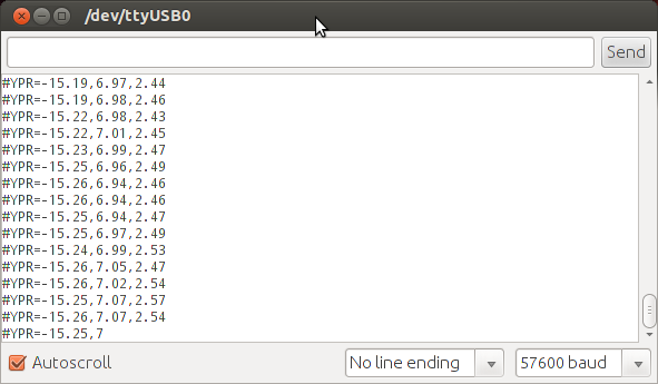
The three numbers represent YPR (Yaw, Pitch, and Roll) in degrees.
3D Visualization Test GUI
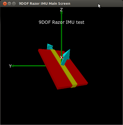
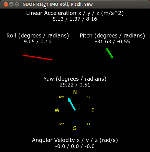
You can also use the included 3D Visualization Test GUI to test the AHRS. Simply run the launch file:
roslaunch razor_imu_9dof razor-pub-and-display.launch
You should see a display like this:
Echo the Imu Messages
The normal way to start publishing Imu data from the Razor is to run the launch file:
roslaunch razor_imu_9dof razor-pub.launch
You can now run "rostopic list" in another window and look for the /imu topic. Run "rostopic echo /imu" and look at the Imu messages. Move the Razor around and see how the values in the Imu messages change.
Sensor Calibration
Depending on how good or bad your sensors are, precision and responsiveness of the Razor AHRS can be improved a lot by calibrating the sensors. If not calibrated you may get effects like
drifts in yaw when you apply roll to the board.
pointing up does not really result in an up attitude.
Based on the calibration measurements you compile into the firmware the firmware tries to compensate all three sensors for:
- wrongly scaled sensor axes: e.g. if the accelerometer x-axis measures 200 units, whereas the accelerometer y-axis measures 230 units with the same force applied. All three axes per sensor should be consistent.
- zero offsets: e.g. if any of the gyroscope axes reports something different than zero when the board is not moving.
Right now these compensations are not adaptive over time. They stay the same and they’re only as good as the calibration measurements you hardcode into the firmware.
The magnetometer has some particularities when it comes to calibration, since there are not only internal sensor inaccuracy and noise, but also external magnetic field distortions. Good magnetometer performance is most crucial to yield a correct heading in all directions - so if you calibrate in a distorted environment, you will always have errors.
There are several types of magnetic field distortions. First of all there is soft iron and hard iron distortion. Second, the source(s) of distortion can be relative to the sensor (i.e. moving and rotating with the sensor) or independent from the sensor (bound to the world or moving independently in the world). To learn about soft iron and hard iron distortion and possible compensation approaches, have a look here, here and here.
Currently the calibration compensates for *hard* and *soft iron* errors, where the *iron* moves/rotates with the sensor. Compensating for *hard/soft iron* errors where the source of distortion is not bound to the sensor is only possible to a certain degree and requires quite complex adaptive algorithms. There are no plans on adding compensation for these kinds of errors in the near future.
Calibration Procedure
Power up the Razor a few minutes before calibration, so the sensors can warm up. Calibrating the sensors can be a little tricky:
Open $(find razor_imu_9dof)/src/Razor_AHRS/Razor_AHRS.ino using Arduino and find the section "USER SETUP AREA" / "SENSOR CALIBRATION". This is where you put the calibration values later.
Connect the Razor to your computer, set the correct serial port in Arduino and open the Serial Monitor.
- If you didn’t change the firmware defaults, you should see lots of output like this:
#YPR=-155.73,-76.48,-129.51
Set the firmware output mode to calibration by sending the string #oc. You should now see output like this:
accel x,y,z (min/max) = -5.00/-1.00 25.00/29.00 225.00/232.00
Calibrating the Accelerometer
We'll try to find the minimum and maximum output values for the earth gravitation on each axis. When you move the board, move it real slowly, so the acceleration you apply to it is as small as possible. We only want pure gravity!
- Take the board and point straight down with the x-axis (remember: x-axis = towards the short edge with the connector holes). While you do that, you can see the x-maximum (the second value) getting bigger.
Hold the board very still and reset the measurement by sending #oc again.
- Now carefully tilt the board a little in every direction until the value does not get bigger any more and write down the x-maximum value.
Do the same thing for the opposite side (x-axis pointing up) to get the x-minimum: bring into position, send #oc to reset measurement, find x-minimum value and write it down.
- Do the same thing for the z-axis (down and up) and the y-axis (right and left).
If you think you messed up the measurement by shaking or moving the board too fast, you can always reset by sending #oc.
You should now have all the min/max values. Put them into Razor_AHRS.ino.
CAUTION: You have to be really careful when doing this! Even slightly tapping the board with the finger messes up the measurement (try it!) and leads to wrong calibration. Use #oc very often and double check your min/max values)
Calibrating the gyroscope
Lay the Razor AHRS still on the table.
We’re still in calibration mode for the accelerometer. Send #on twice, which will move calibration past the magnetometer to the gyroscope.
Wait for 10 seconds, and do not move the Razor AHRS. It will collect and average the noise of the gyroscope on all three axes.
- You should now have output that looks like this:
gyro x,y,z (current/average) = -29.00/-27.98 102.00/100.51 -5.00/-5.85
If you think you messed up the measurement by shaking or moving the board, you can reset by sending #oc.
Take the second values of each pair and put them into Razor_AHRS.ino.
Calibrating the magnetometer
This procedure compensates for hard and soft iron errors. Still, in both cases the source of distortion has to be fixed in the sensor coordinate system, i.e. moving and rotating with the sensor.
- To start calibrating, put the sensor in the magnetic environment where it will be used later - e.g. in the exact spot on your robot. Robots have strong magnets in their motors, and magnetometers are frequently mounted above the robot to create a physical separation.
Use one of the procedures in the 'Testing the AHRS' section to display Razor AHRS output
Test whether the sensor is affected by proximity to the robot. Move the Razor AHRS closer and further away from the robot while holding its attitude constant, and make sure readings at your desired mounting location aren't affected by proximity to the robot.
Test whether the sensor is affected when the motors run. Run the robot motors forward and backward (with the robot up on a stand!). If the output changes, you need to move the Razor AHRS further away from the robot.
Download and install Processing. We will use it to compile and run the test program. Any Processing versions 2.x should work fine, tested with version 2.0.3.
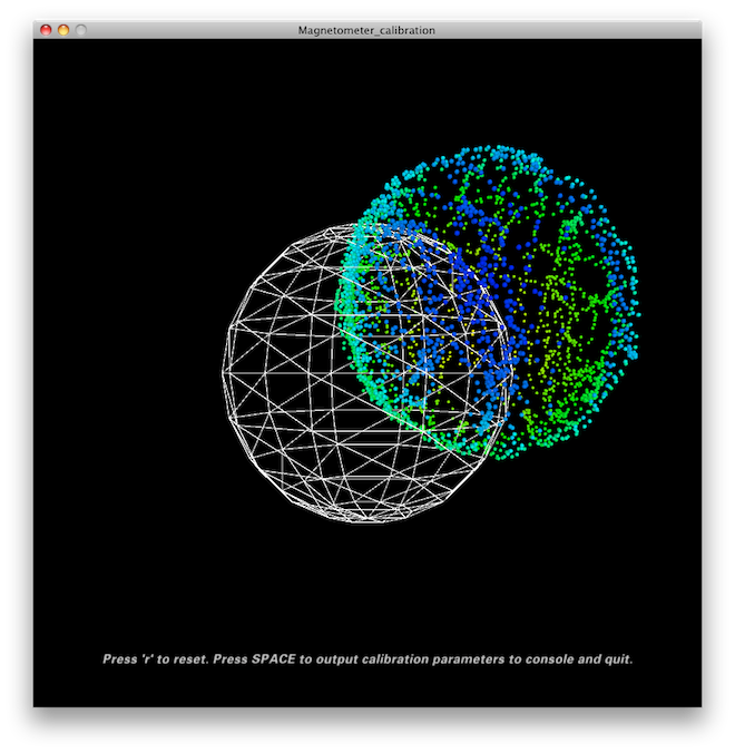
Quit all applications that read from the sensor (e.g. Serial Monitor, 3D Visualization GUI, …) and run the Processing magnetometer calibration sketch located in $(find razor_imu_9dof)/magnetometer_calibration/Processing/Magnetometer_calibration. Note: you have to install the EJML library first, or else the sketch won’t run. How to do that? Have a look at the NOTE at the top of Magnetometer_calibration.pde.
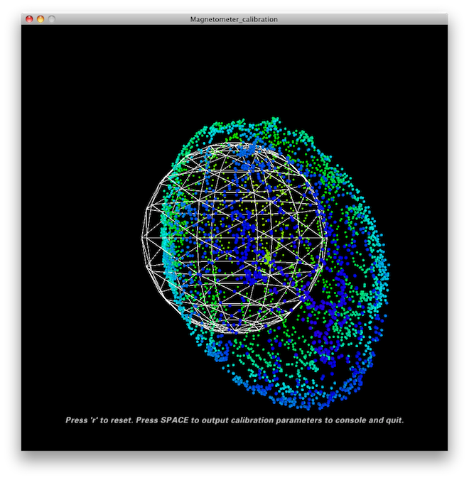
- Try to rotate the sensor in a way so that you cover all orientations so you produce dots that more or less evenly cover the sphere.
- In a mostly undistorted environment this could look something like this:
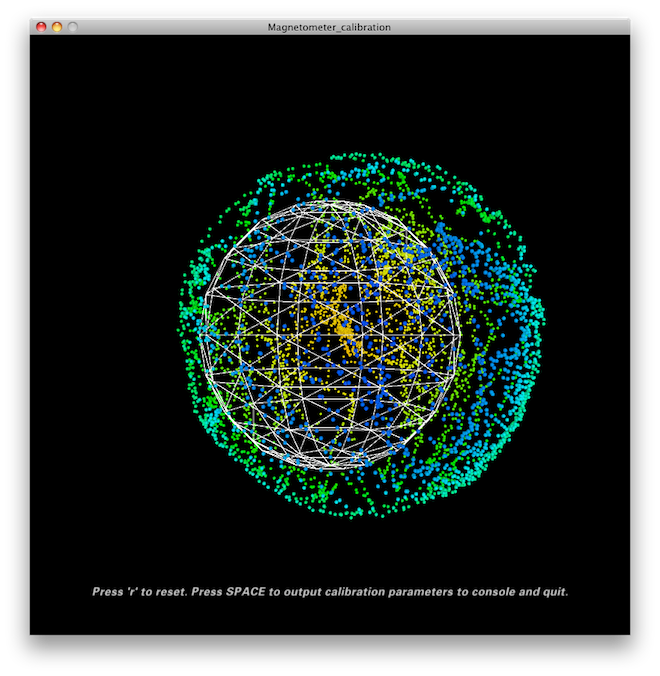
Hit SPACE and watch the Processing console - you’ll find some lines of code that you have to put into the firmware under "USER SETUP AREA" / "SENSOR CALIBRATION" and then you’re done.
Matlab analysis of magnetometer calibration (optional)
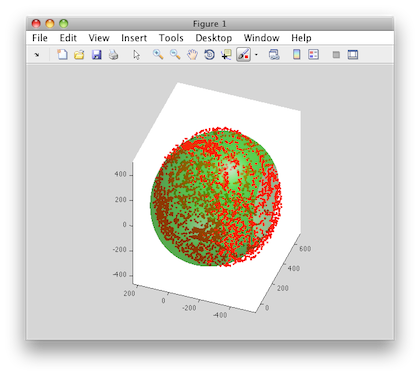
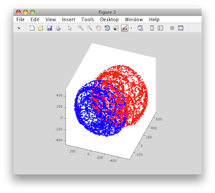
The collected data (the dots) are also written to a file magnetom.float in the sketch folder. If you own Matlab, under $(find razor_imu_9dof)/magnetometer_calibration/Matlab/magnetometer_calibration you’ll find a script called magnetometer_calibration.m that uses this file and produces some plots for you, so you can visually check the calibration.
Ellipsoid fit and corrected values:
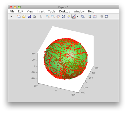
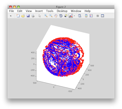
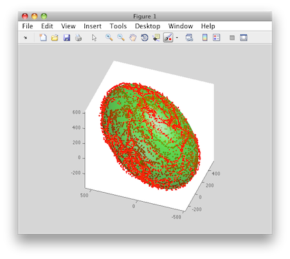
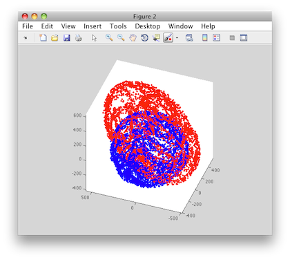
Another calibration example: Soft iron gives a sphere scaled and distorted into an ellipsoid.
- Sampled raw magnetometer values:
- Ellipsoid fit and corrected values:
Another calibration example: Hard iron gives an offset sphere.
- Sampled raw magnetometer values:
- Ellipsoid fit and corrected values:
Hints and Known Bugs
- You should avoid magnetic field distortions (e.g. from metal objects and electronic devices nearby).
- In few cases Razor AHRS can become confused (magnetic field distortions?) and starts acting weird. It seems like the magnetometer becomes "locked", resulting in the heading always drifting/converging back to the same angle. Resetting the microcontroller which runs the Razor AHRS firmware does not help in this case (so it's not a firmware bug!), but turning power off and on again should do the trick. I think this must be a bug inside the magnetometer.
Acknowledgement
Much of this page was derived from Peter Bartz' AHRS tutorial which is licensed under a Creative Commons Attribution-NonCommercial-ShareAlike 3.0 Unported License. The AHRS firmware is licensed under GPLv3.
Contents
Description
This is a driver package for the Sparkfun Razor IMU 9DOF (Degree of freedom) sensor boards SEN-10736 and SEN-10125 from https://www.sparkfun.com/products/10736. The Razor board contains a 3-axis magnetometer, gyro and accelerometer. The driver should also work with the SEN-10724 9-DOF sensor stick, but you will have to figure out how to connect the sensor stick to the arduino and modify the firmware appropriately - the maintainer of this package will not support you. Older versions of the Razor are not supported.
The Razor has an onboard Arduino which runs Attitude Heading Reporting System (AHRS) firmware that works with this ROS driver. You have to load the ROS AHRS firmware onto it using the Arduino IDE. (The board as shipped from Sparkfun only contains sensor-value-printing firmware.) The ROS version of the AHRS firmware is in this package, and is derived from the original AHRS Razor firmware by Peter Bartz. The original source is maintained here and an excellent tutorial is on the corresponding wiki page
A 3D visualization testing application is included in this package.
Installation
Install Arduino http://arduino.cc/en/main/software IDE for upload custom firmware to Razor board.
Install python visual package at http://www.vpython.org/contents/download_linux.html
$rosmake razor_imu_9dof
Video
This is a 3D visualization demonstration for Razor IMU 9DOF ROS package
Report a bug
Please email to me: tang.tiong.yew at monash dot edu
You can file your feedback ticket at below link. You are welcome to join develop this package.
